dmx wiring diagram
DMX Pinouts and Wiring. 5 Pin Dmx Wiring Diagram.
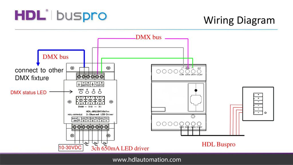
Dmx Controller Sb Dn 48dmx Ppt Download
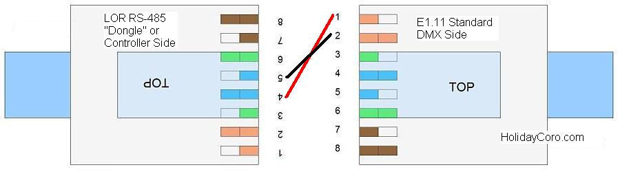
Dmx pinout rj45 dmx512 pinoutguide.

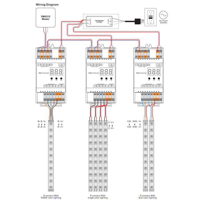
. Wiring diagrams are examples of typical installations intended to illustrate the number of wires. DMX to TM1809 Decoder Support WS2811 TM1803TM1804TM1809TM1812 IC. And also DIY USB DMX.
Decoder wiring dmx rgbw dmx512 bincolor. XLR Connectors are used extensively in both audio and lighting. The DMX data itself requires only 2 of.
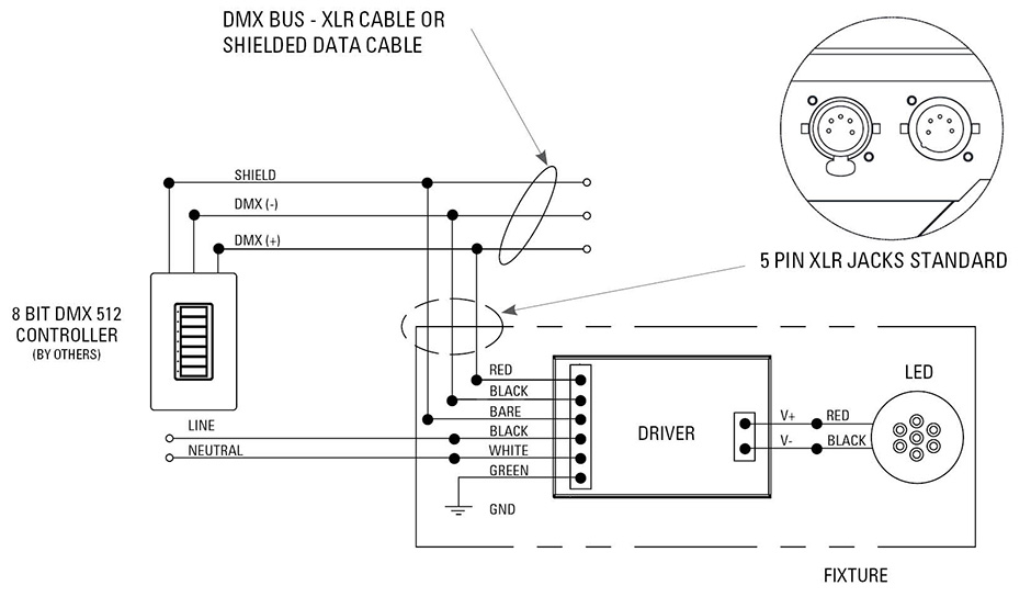
WIRING INSTRUCTIONS DMX Dimming Page 1 DIMMING DRIVER WIRING SCHEMES. DMX 3 pin to 5 pin Wiring. 5 Channel LED DMX.
When you make use of your finger or even stick to the circuit along with your. Cat5 or equivalent is not preferred as a portable cable since it is not as rugged as other DMX. 18 Pics about DMX to TM1809 Decoder Support WS2811 TM1803TM1804TM1809TM1812 IC.
Each terminal accepts up to two 18 AWG 10 mm2 wires. Dmx Controller Wiring Diagram. By Anthony Eden January 21 2014 Support Centre.
June 8 2022 April 11 2022 by Krystina Yestramski. SELV PELV NECR Class 2 wiring with line voltagemains wiring. Connect the network cables DMX DMX- and DMX shielding wire the orangewhite orange and brown wire in a CAT5 cable to the DMX in DMX in- and DMX in shield connector respectively.
And show address via digital numueric display. However ETC supports DMX over CAT5 with maximum total wire length per run of 500m 1640ft. Read wiring diagrams from negative to positive plus redraw the routine as a straight collection.
Usb To Dmx Wiring Diagram USB Wiring Diagram Pin en Cables conexiones y más. Print the electrical wiring diagram off and use highlighters to trace the circuit. Utp cat5 or cat6 network cable is another option but it has a slightly lower impedance of 100ω Pinout standards for dmx.
16-Bit DMX Receiver decoder 4 Output Channels 5 Amps. The QSE-CI-DMX consumes 2 power draw units on the QS link. Pinouts Devices Connectors.
The pwm signals control led drivers output boards mosfetresistor based regulation or constant current. 17 Pictures about 5 Pin Dmx Wiring Diagram. In general the final empty DMX out connector should have a DMX512 terminating plug attached into it which is simply a 120ohm resistor joining pins 2 and 3 of the connector.
3 Pin Dmx Cable Wiring Diagram. All circuits are the same. Dmx 512 wiring diagram Stage dj light controller lighting 1024 ch dmx 512 party pub.
DMX cables are most commonly made with 2 core shielded data cable terminated at either end with 3 or 5 pin XLR connectors one male one female. Traditionally 3 pin connectors have been the. 5 Pin Dmx Wiring Diagram Source.
Installation grade dmx to spi pixel converter for led control enttec 576w 3chs rgb. Pinout of DMX DMX512 RJ-45DMX Digital MultipleX is a communications protocol used mainly to control stage lighting. With the right DMX cable at your disposal there are a plethora of ways to make the connection CueServer supports up to 7 different standard connection types.
Dmx Adapter Leads Auschristmaslighting
![]()
Led Dmx512 Zu Spi Decoder Konverter 5v 12v 24v Dmx Slave Ttl Pixel Controller Unterstutzung 6803 8806 2811 2812 2801 3001 9813 Ic Rgb Controller Aliexpress

Dmx Rgb Mixer For Lights Arduino Project Hub

How To Wire A Dmx System With Rgb Colour Led Strip Lights Wiring Diagram Led Strip Lighting Strip Lighting Led Lighting Diy
Dmx Dimming Solutions Usai

Amazon Com Cable Matters 2 Pack 5 Pin To 3 Pin Dmx Lighting Cable 6 Inches 5 Pin Male To 3 Pin Female Xlr Cable 3 Pin To 5 Pin Dmx Adapter Cable In Black Musical Instruments
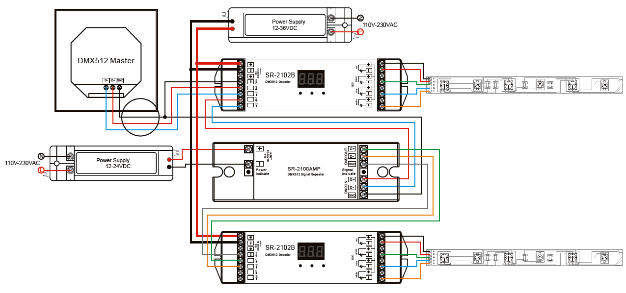
Dmx512 Signal Amplifier Sr 2100amp
Led Tutorials Dmx Led Control Installation
Kb Results

Make A Dmx Tester

Dmx512 Wikipedia
Slc Dmx Controller Cv 4x5a 12 36v Rgbw Din The Light Group

Zaniboni Lighting Wiring Diagrams Part 1 Led Lighting
![]()
Wiring Diagram Pinout Rj 45 Dmx512 Electrical Wires Cable Receive Signal Angle Text Rectangle Png Pngwing

Outdoor Dmx 512 Decoder Hueda H 2102b W Led World Lighting
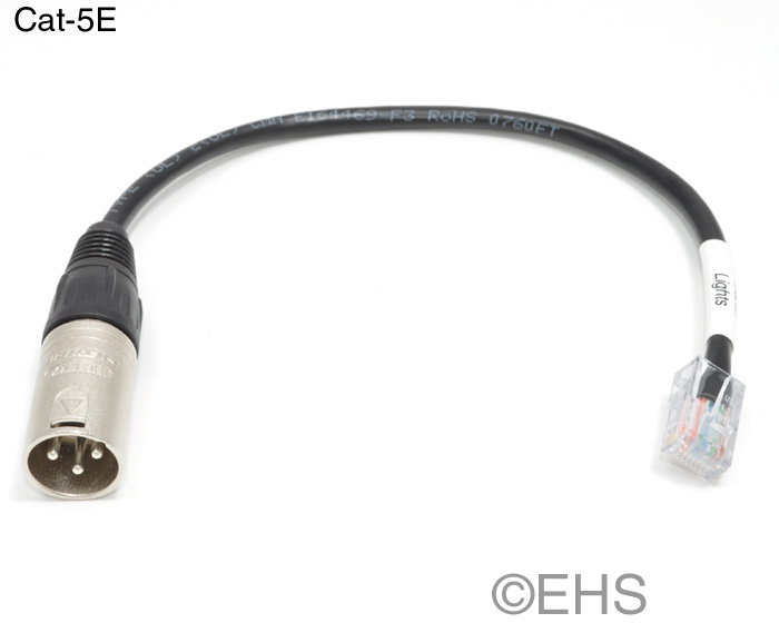
Dmx 3 Pin Xlr Male To Rj 45 Adapter Event Horizon Services

Dmx 3 Pin To 5 Pin Wiring